Baghouse fit and component guide
For maintenance engineers, MRO buyers, and cage or bag sourcing teams
Reviewed by FilterBagWorks Technical Team
How to Measure a Baghouse Filter Cage and Match It to the Filter Bag
Measure the cage body OD and overall-length endpoints, then record wires, rings, top, bottom, venturi, condition, and the matching bag relationship. Photos and dimensions support a replacement review, but nominal diameter and length alone do not prove fit.
Direct answer
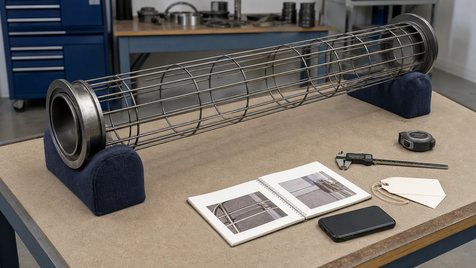
Measure a baghouse filter cage as a connected component, not as a nominal cylinder. Record buyer-entered units and exact reference points for body outside diameter, overall length, wires, rings, top, bottom, venturi, joint, material evidence, and condition. Then photograph how the cage seats in the bag and collector. Mark every value measured, copied, observed, assumed, or unknown; final fit requires the controlling collector and bag evidence.
Scope, safety boundary, and evidence status
This workflow is for documenting a safely removed baghouse cage, its related bag, and accessible mating evidence for replacement review. It is not an instruction to enter a collector, bypass isolation, handle contaminated parts without the site-required controls, or measure moving or energized equipment. OSHA explains that electrical, mechanical, pneumatic, thermal, chemical, and other stored energy can seriously injure workers during service, and an equipment-specific Donaldson manual requires power off and lockout before maintenance. [2] [3] Follow the collector manual, employer procedures, contaminant controls, lifting plan, and qualified safety direction. Record each field as M measured, C copied from an identified record, O observed, A assumed but unverified, or U unknown. Never promote A or U to an ordering value.
Measure the cage in this exact field sequence
Start with a full-cage photo, assign the removed cage a neutral reference, choose one unit system for the worksheet, and place the cage on clean padded supports so it is not carrying its weight on a top flange, venturi, joint, or damaged wire. Photograph the tool position for every fit-critical reading. If an approved drawing or purchase record is available, keep copied values beside—not in place of—the field measurements and identify the record revision.
1. Record cage outside diameter and the measurement location
Measure the cage body OD across the outer wire surfaces at an undamaged, straight body location—not across a top flange, roll band, bottom cap, venturi, or obvious bend. Enter the value and unit, then write the distance or ring reference that identifies the location. A recognized field guide notes that some bottom pans differ from the cage body and therefore should not substitute for a body-diameter reading. [4] If roundness is uncertain, record a second direction at the same location and another undamaged body position. Report all readings; do not average away a possible bend or declare a tolerance.
2. Define and measure the overall-length reference
Write the endpoints before writing the length. For example: outermost top-flange face to outermost bottom-cap face, including the integral venturi projection; or cage-body seating shoulder to bottom-cap face, excluding a removable venturi. Photograph both endpoints with arrows on a separate sketch. For a split cage, record assembled overall length as its own field after the section and joint measurements. Do not compare two length values until both records use the same endpoints. A bent cap, unseated joint, or detached top makes the field damaged or incomplete, not nominal.
3. Count the vertical wires
Choose one longitudinal wire as the start, mark it with a removable blank tag, and count once around the full circumference until returning to that wire. Record the count as observed and add an overall end-view photo that shows the count path. Do not infer the wire count from a product family, an incomplete photo, or a common configuration. Industry references treat longitudinal or stringer-wire count as a cage construction field, but example counts belong to the products or fabric constructions described by those sources—not to every collector.
4. Measure vertical-wire diameter
Use a suitable caliper on a clean, accessible, straight portion of one vertical wire between welds. Record the tool, location, value, and unit. If a coating remains on the wire, state that the reading includes the coating; do not subtract an estimated coating thickness. Repeat on another undamaged wire when corrosion, buildup, flattening, or visible variation could affect the reading. A corrosion-reduced or damaged-wire reading is condition evidence and must not be copied into the intended replacement specification without another reliable reference.
5. Count support rings and measure the spacing pattern
Count every support ring and identify whether the top and bottom structural rings are included in your count. Measure spacing from ring centerline to ring centerline, beginning at a named top reference and proceeding in order toward the bottom. List each interval or identify repeated intervals plus exceptions; do not write “even” from appearance alone. Industry measurement guidance specifically notes that the last interval can differ from the others. [4] Record both end intervals, the unit, and any ring displaced by damage. No universal ring spacing is implied.
6. Document the cage top style
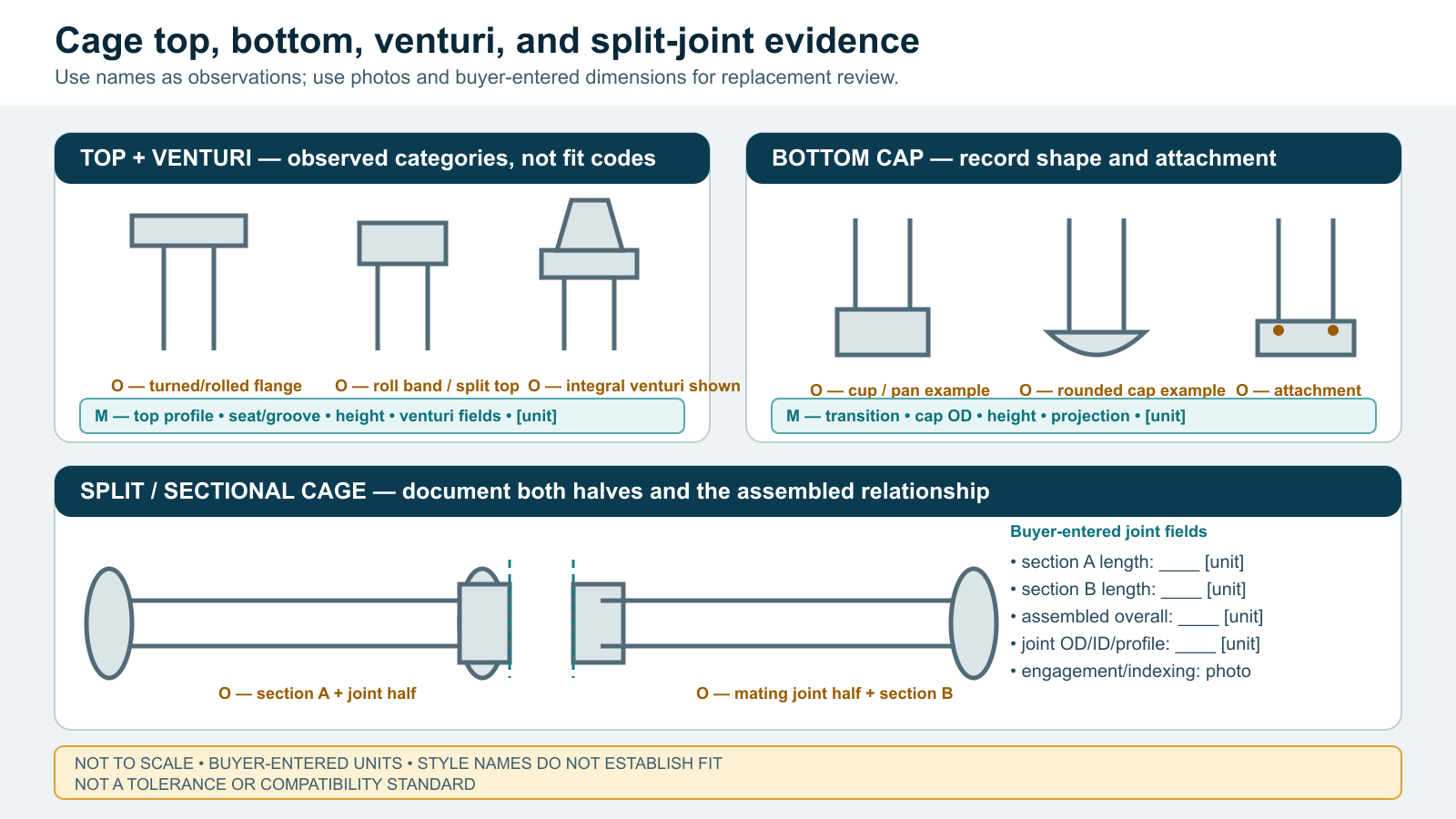
Photograph the top straight-on, from the side, and from inside the cage. Describe what is observed—such as a turned or rolled flange, straight flange, roll band, split/rolled collar, detachable top, or another profile—without assuming the supplier's name for it. Measure the body-to-top transition, outside and inside features that mate or seat, groove or shoulder location, overall top height, and any projection, using named reference faces. Note installed direction and whether the top supports, locates, hangs, or seats the cage. A style name or silhouette alone does not establish fit.
7. Document the bottom cap and wire attachment
Photograph the bottom face, side profile, body-to-cap transition, and wire attachment. Record whether the observed part looks like a cup, pan, disc, rounded cap, open frame, or another construction; then measure the cap outside diameter, height, projection beyond the body, and the reference used. Note whether wires appear welded inside, outside, or into another feature and whether the edge is smooth, distorted, or damaged. Manufacturer literature illustrates different bottom and edge constructions, but those examples are product-specific and do not set a universal requirement.
8. Record the venturi as a separate fit relationship
State present, absent, or unknown. If present, record whether the venturi is integral, welded, detachable/drop-in, or otherwise attached; photograph its orientation and the cage-top mating detail. Measure opening or throat, inlet and outlet diameters where identifiable, overall height, flange or seating geometry, and relevant projection, always with endpoints and units. EPA describes a venturi in a pulse-jet cleaning arrangement, while industry sources show integral and separate versions. [1] [4] Do not conclude that every collector needs one or that matching outer shape proves cleaning compatibility.
9. Measure every split-cage section and joint
Record one-piece or split/sectional construction and the number and installed order of sections. For each section, name its top and bottom endpoint and record its free length. Photograph both joint halves before assembly, during engagement if site procedures permit, and fully assembled on supports. Record joint OD/ID or profile, overlap or engagement evidence, locking or indexing feature, assembled reference, and whether a section can rotate. Also document clean-plenum or access constraints from approved records or safe exterior evidence. Do not prescribe a minimum engagement or assume two joints with similar names interchange.
10. Separate material and coating evidence from appearance
Copy a material or coating only from an identified drawing, label, certificate, purchase record, or supported test result. Industry literature recognizes low-carbon/plain steel, galvanized steel, stainless materials, and coated cage constructions. [5] Appearance may support an observed description—bright metallic, dark coating, flaking layer, discoloration—but cannot prove alloy grade, stainless grade, galvanizing, coating chemistry, or thickness. Write “material unknown” or “coating unknown” when the evidence is missing, and include dust, moisture, chemistry, temperature, and upset history for project-specific review.
11. Inspect and map corrosion
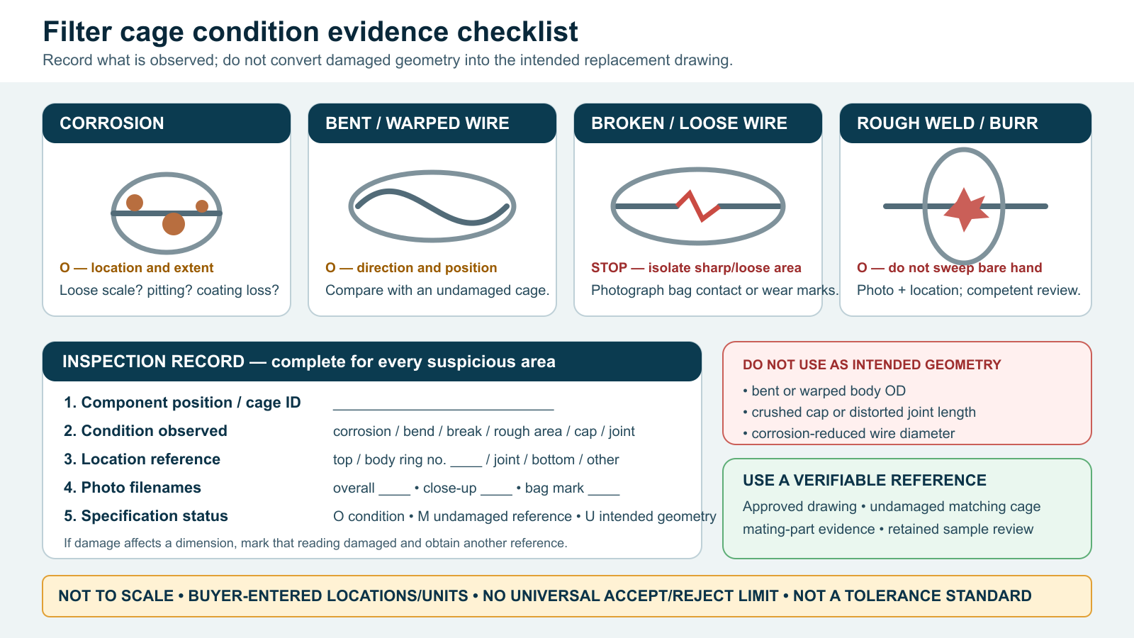
Map corrosion by cage reference: top, ring number, wire number or clock position, joint, and bottom. Photograph an overall view and a close view with a neutral location marker. Describe surface discoloration, coating loss, loose scale, pitting, reduced section, or an uncertain deposit without assigning a mechanism from appearance. Donaldson’s maintenance guidance includes filter/cage condition in periodic review. [6] The source does not provide a universal accept/reject corrosion threshold, and neither does this guide. Route the actual evidence, operating context, and bag marks for competent disposition.
12. Record bent, warped, broken, or loose wires
Sight along the supported cage from both ends and rotate only if the handling plan permits. Record any bow, twist, flat area, shifted ring, broken wire, loose wire, or distorted top/bottom/joint by the same location system used for the photos. Keep sharp or loose areas isolated and follow site handling controls. Do not use the distorted OD, length, or joint position as intended geometry. Compare with an undamaged matching cage, an approved drawing, the mating bag and collector evidence, or a retained sample. If no reference exists, mark the intended value unknown and request review.
13. Inspect rough welds, burrs, and contact edges
Use good light and close photographs to review wire-to-ring welds, top and bottom attachments, cap edges, and joint surfaces. Do not sweep a bare hand over a suspected burr or sharp edge. Parker describes polished ring welds and rounded edges as abrasion-reduction features in its cage construction. [5] That is useful inspection context, not a universal weld-quality standard. Record the observed rough area, its location, associated bag wear, and whether the condition affects a measurement; leave acceptance and repair to the controlling specification and competent reviewer.
14. Match the cage record to the filter bag and collector
Lay the documented cage record beside the bag record: bag body size and measurement method, overall-length endpoints, top attachment and seal, bottom construction, seam and wear locations, current media when supported, and installed orientation. Add the tube-sheet opening, seating surfaces, access direction, blowpipe or cleaning relationship, and venturi position when safely documented. One Donaldson LP manual shows its cage seating inside a snap-band bag at the tube sheet, which demonstrates why mating components must be recorded together but is not a universal installation method. [3] Do not calculate a universal clearance from nominal diameters.
15. Create the dimensioned cage drawing and evidence index
Draw one side view, one top/end view, the bottom profile, the venturi detail, and both halves of every joint. Give each field an M/C/O/A/U status, value, unit, endpoint or location, tool or record source, photo filename, and reviewer question. Put damaged readings in a condition layer, not the intended-geometry layer. Add collector maker/model/serial when known, position, bag reference, installed quantity, requested quantity, process and dust, cleaning method, temperature and moisture context, reason for replacement, and sample availability. The drawing is a traceable RFQ record—not a compatibility certificate.
Field measurement and condition assets
Use the three editable diagrams to keep dimensions, construction observations, and damage evidence separate. Every blank is buyer-entered; the drawings are not to scale and do not state a tolerance, clearance, compatibility rule, repair criterion, or collector-specific acceptance limit. Use the existing five-page baghouse fit PDF as the cover worksheet so the bag, cage, venturi, operating context, and purchasing details stay in one evidence package.
Scroll table horizontally
| Evidence layer | Record | Do not convert it into |
|---|---|---|
| Measured (M) | Value, unit, tool, location, endpoints, photo | A universal nominal size or tolerance |
| Copied (C) | Exact value plus record title, revision, and owner | A field measurement or current-as-built fact |
| Observed (O) | Style, attachment, condition, installed relationship | A material grade, fit result, or accepted defect |
| Assumed (A) | Working idea and the verification needed | An ordering value |
| Unknown (U) | Missing field and responsible verification path | A guessed value |
| Damage evidence | Location, photo, associated bag mark, affected reading | Intended cage geometry |
On narrow screens, scroll horizontally to inspect the full-size diagram.
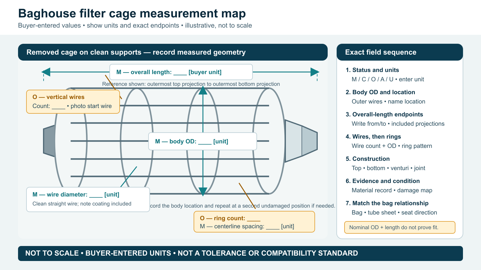
On narrow screens, scroll horizontally to inspect the full-size diagram.
On narrow screens, scroll horizontally to inspect the full-size diagram.
Common cage-measurement mistakes and red flags
Stop the release when the replacement decision depends on an unstated endpoint, a damaged dimension, or a style name treated as proof of fit.
- Reporting diameter without the body location or including the top flange or bottom cap.
- Comparing lengths that use different top, venturi, joint, or bottom endpoints.
- Writing one ring-spacing value when end intervals or a pattern differ.
- Calling a copied drawing value measured, or a material/coating known from appearance.
- Measuring a bent cage and treating the damaged shape as the intended replacement geometry.
- Omitting the mating bag top, bottom, tube sheet, seating direction, or cleaning relationship.
- Ordering by nominal OD and length while top, bottom, venturi, joint, material evidence, or condition remains unknown.
- Publishing an example clearance, tolerance, or joint engagement as universal.
Quote-ready cage handoff checklist
Send one indexed folder and one drawing or worksheet. Label uncertainty instead of hiding it.
- Collector maker, model, serial/asset ID, compartment or position, and installed orientation when known.
- One unit system plus M/C/O/A/U status for every field.
- Body OD with location; overall length with written endpoints; each split-section and assembled length.
- Vertical-wire count and diameter; ring count and ordered spacing pattern with end intervals.
- Top profile and mating dimensions; bottom cap profile, transition, attachment, and projection.
- Venturi present/absent/unknown, integral/separate status, opening, height, flange/seat, and orientation.
- Joint photos, geometry, engagement/indexing evidence, section order, and access constraint.
- Material/coating record source or explicit unknown; corrosion, bends, breaks, rough welds, and bag marks mapped separately.
- Matching bag body and length references, top, bottom, seal, seam, media record, tube sheet, and seating relationship.
- Dust/process, cleaning method, temperature/moisture/chemistry context, reason for replacement, quantity, and sample availability.
Product path
- Baghouse filter cagesUse the cage product path after OD, length references, wires, rings, top, bottom, venturi, joint, material evidence, condition, and quantity are documented.
- Matching filter bagsReview the bag path together with the cage record, bag top and bottom, seal, media evidence, tube sheet, and installed relationship.
- Venturis and cage accessoriesUse the accessory path when the venturi, cage top/bottom, joint, attachment, mating surfaces, dimensions, orientation, and condition are traceable.
Frequently asked questions
Where should I measure a baghouse filter cage outside diameter?
Measure across the outer wire surfaces at a straight, undamaged cage-body location. Do not substitute a top flange, roll band, bottom cap, venturi, or obvious bend for the body OD. Record the exact location, direction, value, unit, tool, and photo; take additional readings when roundness or damage is uncertain.
What endpoints should I use for cage overall length?
Use endpoints that match the actual review and write them explicitly before the value. State whether the measurement runs between outermost projections, seating faces, or body references and whether an integral venturi, flange, cap, or joint is included. For a split cage, record each section and the fully assembled overall reference separately.
How much clearance should there be between a filter bag and cage?
This guide does not publish a universal clearance or pinch. The required relationship depends on the actual bag construction and media, cage geometry, top and bottom, collector arrangement, cleaning method, and controlling drawing or specification. Send both bag and cage evidence and obtain the collector- or project-specific value in writing.
Can I identify cage material or coating by color?
No. Color and surface appearance can be recorded as observations, but they do not prove steel or stainless grade, galvanizing, coating chemistry, or coating thickness. Copy material/coating only from an identified record or supported verification; otherwise mark it unknown and provide the operating and corrosion context.
What should I record for a cage venturi?
Record present, absent, or unknown; integral, welded, detachable, or other attachment; installed orientation; opening or throat; identifiable inlet and outlet diameters; overall height; flange or seating geometry; and cage-top relationship. Use endpoints and units. Similar appearance does not prove that another venturi fits or suits the collector's cleaning design.
Should I use a bent or corroded cage to create the replacement drawing?
Use it to document condition, not automatically as intended geometry. Map the damage and affected readings, then compare an undamaged matching cage, approved drawing, mating components, or retained sample. If the original shape cannot be verified, mark the intended value unknown and request review before ordering.
What photos belong in a cage RFQ package?
Include the entire cage on supports, both ends, body OD tool placement, overall-length endpoints, tagged wire-count start, wire-diameter tool placement, ring pattern, top profile, bottom cap and attachment, venturi, both halves of every joint, material markings, corrosion, bends, breaks, rough weld areas, bag wear marks, matching bag, and safely accessible collector relationship.
Sources
- U.S. EPA: Fabric Filter — Pulse-Jet Cleaned Type (Baghouses)
- OSHA: Control of Hazardous Energy (Lockout/Tagout)
- Donaldson LP Baghouse Installation and Operation Manual
- Baghouse.com: How to Measure Your Baghouse Filters & Cages
- Parker: Baghouse Accessories
- Donaldson: Baghouse Collector Preventative Maintenance
Request a filter review
Send the completed baghouse fit checklist, dimensioned cage sketch, full and detail photos, matching bag and tube-sheet evidence, collector information, quantity, operating context, and an old sample reference when available. Keep measured, copied, observed, assumed, unknown, and damaged fields distinct, and ask the written review to identify conflicts, missing evidence, deviations, and the verification required before ordering.
Request a quoteCatalogue cage-type reference
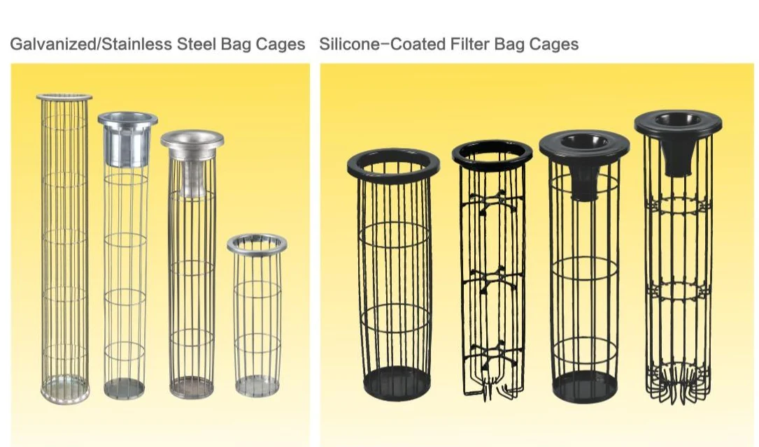
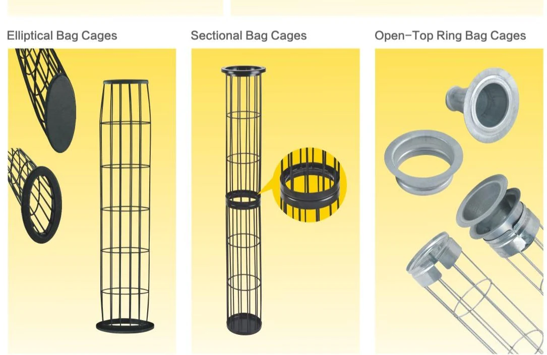
Use the visual family only after recording the actual cage measurements.
Catalogue p. 13 shows material, finish and geometry families. It does not establish a standard diameter, length, wire count, ring spacing, tolerance, metallurgy grade or coating performance.
Galvanized/stainless and silicone-coated cage variants are shown separately.
Elliptical, sectional and open-top-ring cage forms are shown separately.
Diameter, length, wire count, ring spacing, collar, bottom, joining method, finish, photos and any drawing or part number.
First-party source: Guanlin product catalogue, p. 13.